Resource Strategy for Post-Mask Metal-Only Functional ECO
DownloadEasylogicECO White Paper
WP-PMR-01
Functional ECO (Engineering Change Order) is an incremental design method used to revise existing ASIC designs. Once an RTL code is revised to change the ASIC function, the ECO process modifies a portion of the existing netlist to align with the revised ASIC function while preserving the integrity of the overall netlist.
Functional ECO requests have become increasingly common in recent years due to the rising complexity of ASIC design and shorter project cycles. When an RTL change is necessary, re-spinning the entire design often causes project delays. A successful ECO task offers a shortcut for incorporating the required changes swiftly. When the design is at the layout-completed or the already taped-out stage, a successful ECO task can significantly reduce the project delays while maintaining the design quality.
This article examines the available spare resources associated with a post-layout functional ECO task and describes the additional resources deployed by EasylogicECO.
Introduction to Post-Mask ECO
The functional ECO process is divided into two primary aspects:
1. Pre-layout changes, and
2. Post-layout changes.
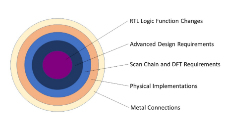
Pre-layout changes involve modifications to the design logic and related implementations of specific design requirements, such as low-power cells and scan chain netlists. On the other hand, post-layout changes are often limited to the metal layers and aim to re-connect available logic resources (referred to as Post-Mask ECO or Metal ECO).
In this paper, our focus will be on the patch implementation and the resource strategy in a post-layout ECO.

Figure 1: Types of data to be revised in a post-mask ECO task
Patch Implementation Criteria in Post-Mask Functional ECO Task
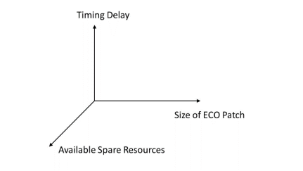
An efficient patch implementation algorithm needs to consider three factors:
1. Timing delay of the revised netlist
2. Available spare resources for patch creation
3. Size of ECO patch
The timing delay of the revised netlist, derived from analyzing the original netlist, represents the target timing for the patch to achieve. The patch logic of the revised function must fulfill the timing requirement using existing spare resources, which are predetermined in terms of cell functions, delays, locations, and quantity. Consequently, the number of available resources ultimately determines the outcome of the patch, including both the timing delay and the patch size.

Figure 2: Trade-off during patch implementation
Overview of Spare Resources for Post-Mask ECO
If a design is layout-complete or already taped-out (so called post-mask), success heavily relies on the spare resources available for patch implementation. The resources used to implement the patch need to be physically located in the vicinity of the ECO net where the revision of the function is necessary.
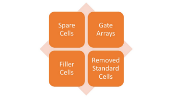
Spare resources for a post-layout functional ECO include four types of logic cells:
1. Spare cells
2. Gate arrays
3. Configurable filler cells
4. Standard cells that are disengaged from the original function as a result of the ECO

Traditional Approaches Employed in Handling Spare Resources
Traditional approaches involve first two types of spare resources:
1. Spare cells
2. Gate arrays
(1) Spare Cells
Spare cells refer to a set of pre-designed standard cells that are not initially used in the main design but are reserved for post-mask modifications. They offer flexibility and enable functional modifications without significant layout changes. The specific types of spare cells used depend on the characteristics of the design, with control logic and combinational logic often requiring different types of spare cells.
There is a limitation on the number of spare cells that can be placed, requiring careful allocation and potentially causing suboptimal usage of available resources.
(2) Gate Arrays
Gate arrays involve predefined arrays of basic logic gates that can be configured to implement specific functions by applying metal-only connections. Gate arrays can be used for targeted changes without requiring extensive design iterations.
However, gate arrays may have higher area and power overhead compared to standard cells. Their usage requires careful planning and integration into the design. Due to their larger size, gate arrays are often placed further away from dense routing areas, possibly introducing timing delay issues.
Spare cells and gate arrays have pros and cons in terms of timing delay, area usage, and power consumption. The trade-off could be driven by specific design applications, as different applications might prefer a specific combination of resources. This white paper focuses solely on demonstrating the fundamental concepts and does not delve into design strategies.
Additional Spare Resources Utilized by EasylogicECO
As the number of available resources is crucial for ECO success, EasylogicECO deploys an innovative algorithm to increase the resources for patch implementation. EasylogicECO utilizes the following two types of additional resources:
1. Configurable filler cells
2. Standard cells that are disengaged from the original netlist as part of the functional ECO
This advanced approach significantly increases the number of resources and enhances the likelihood of achieving success in post-mask ECO.
(1) Filler Cells
Filler cells are additional cells incorporated into the layout to enhance manufacturing yield. They possess a complete gate structure with assigned VDD/VSS pins, adhering to the layout rules of a standard cell. However, they lack logical functionality as their metal layers remain open by design.
Filler cells that establish contact connections with poly, diffusion, and metal 1 layers can be utilized to construct functional gates. Like configuring gate arrays, filler cells use metal connection layers to configure the cell into specific functions. This technology is well-suited for functional ECO involving a small patch without necessitating extensive design alterations.
(2) Disengaged Standard Cells
Functional ECO cases often involve adding new logic gates while simultaneously removing some original gates. The removed gates are typically located near the ECO point, making them the optimal choice for implementing the patch. The reuse of these disengaged standard cells from the original netlist introduces an intriguing concept that offers valuable benefits in terms of routing delay and design flexibility.
Let's consider the following example: an ECO task involving adding 30 gates to create a patch while disengaging 20 original gates. EasylogicECO examines the removed circuit, and if 10 out of those 20 disengaged gates can be reused, it reduces the number of required spare cells from 30 to 20. This approach can double the success rate in certain cases.
Selection Techniques to Best Utilize Available Spare Resources
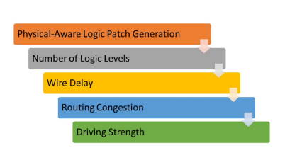
EasylogicECO employs a patented algorithm to optimize timing delays for post-layout functional ECO jobs. Alongside utilizing additional spare resources, the patch implementation process incorporates specific resource selection techniques to ensure an optimal optimization result. These techniques, illustrated in Figure 3, include:

Figure 3: Resource selection techniques for best patch result
1. Physical-aware patch generation
The physical information of the design and the available spare resources, obtained from LEF/DEF input and library files, is used to generate a patch to achieve the timing delay requirements.
2. Number of logic levels
To meet timing requirements, EasylogicECO analyzes the original design logic and the available physical information to arrive at the suitable range of logic levels. This analysis result is then used in patch optimization.
3. Wire delay
As wire delays play a critical role, EasylogicECO estimates the routing delay by leveraging the physical information from the netlist and the user-provided spare resources.
4. Routing congestion
Routability is taken into consideration during cell selections, incorporating a congestion factor within the optimization algorithm. This factor assesses the number of connected gates in the surrounding area of the target spare instance.
5. Driving strength
Based on the fanout requirements and estimated wire lengths, cell selections for the post-mask patch will prioritize cells with appropriate driving strength.
Conclusion
By utilizing additional spare resources and considering critical timing factors in the physical optimization for post-mask functional ECO, EasylogicECO efficiently delivers patches that meet the required timing delays while minimizing tool execution time.
About the author
Kager Tsai
Vice President of Technical Support, Easy-Logic Technology
Since joining Easy-Logic Technology in 2021, Kager has been instrumental in leading his team to offer top-notch technical support to users globally. With 18 years of experience in the CAD industry and has worked for companies such as SiS, MStar, MTK, and Cadence, Kager is proficient in the ASIC front-end tool flow, especially in formal verification and ECO-related applications. Kager also participated in the development of many advanced ECO tool features. |
|