Performing Scan Chain Fixing during Functional ECO Process
DownloadScanChainECO Application note
App-DFT-01
ScanChainECO brings three major benefits in DFT to its users:
1. Automatic scan chain stitching,
2. Automatic balancing of scan chain length, and
3. Manual stitching for greater freedom of DFT design rules.
Therefore, it significantly shortens the time required for each functional ECO task. This application note provides a brief introduction to how ScanChainECO handles the addition and removal of Scan DFFs.
Overview
Generally, after a functional ECO, if there are new or deleted DFFs on the scan chain, the user must manually perform the scan chain stitching. Manual work can be done if the number of new or deleted DFFs is small. However, once the number of affected DFFs increases, designers must spend a lot of time on tracing relevant scan chain information such as scan clock source, each chain length, scan-related functionality, compressor circuits, etc. Fixing the scan chain is not only a non-production work, but also a complex job. This work often exceeds human capabilities, causing designers to give up the DFT coverage of these affected DFFs, and even give up the ECO altogether.
For designers looking to fix scan chains, Easylogic's solution is an invaluable resource
Major Features of ScanChainECO
ScanChainECO can produce excellent results in the following four areas:
• Automatic scan chain stitching
• Automatic scan chain balancing
• Optional manual stitching function
• Manually remove test registers connected to the scan chain.
Details for each of these functions are explained below.
(1) Automatic Scan Chain Stitching
The automatic scan chain stitching function helps users complete scan chain ECO in the shortest possible time, avoiding human errors that may occur during the tedious manual scan chain handling.
Based on the Disable DFT constraints provided by the user, the algorithm built into ScanChainECO first separates the DFT function from the logic function. Subsequently, it tracks the relevant scan chains based on the compressor tail input pins declared by the user. If there is an SDFF that needs to be removed, the SDFF/Q and SDFF/SI of this SDFF will be tied together. Conversely, if there is a new DFF that needs to be added to the chain, ScanChainECO will automatically insert it to a suitable location based on the conditions in the parent module of the new DFF, such as clock source and chain length, and ensure that the result meets the DRC requirements in DFT.
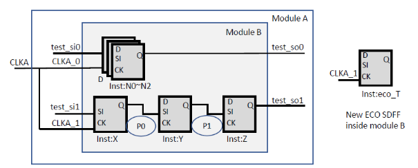
In the example below (Figure 1), if Inst:X and Inst:Z are connected to the compressor circuit, and the clock source of the newly added DFF in the ECO is CLKA_1, and it is inside module B, ScanChainECO will connect the new DFF to either net P0 or net P1. If P0 is closer to the middle point of the entire chain, eco_T will be connected to P0, otherwise it will be connected to P1.

Figure 1: Automatically connecting the new ECO SDFF to net P0 or net P1
(2) Automatic chain length balancing
In addition to saving ECO turnaround time, automatic scan chain balancing ensures that the chip testing cost will not increase due to the ECO.
As mentioned earlier, ScanChainECO will automatically track the length of all scan chains based on user's relevant settings, and insert the new ECO DFF to the existing chain, in the meantime, ensure that the length of the scan chain is within the required range. Users can use the following constraint to limit the length of all scan chains in the chip, which will also help balancing.
set_max_chain_length

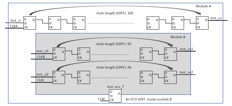
Figure 2: Automatic chain length balancing
If any condition for stitching the scan chain cannot be met (such as the requirements for max chain length or same clock source), it will be determined as a failure and provide such message in the log file.
In the example (Figure 2), assuming the longest chain length is 100, and the clock source of the newly added ECO DFF is CLKC and it is inside module B, eco_T will be inserted to the middle point between test_si2 and test_so2, which is the 49th position.
If ScanChainECO cannot fulfill user's maximum chain length requirements, it will give up the job and display the failure message in the log file. Here is an example (Figure 3).

Figure 3: Failure message of chain length balancing
(3) Manual Stitching
Manual stitching is an additional feature that gives users greater freedom in complying with their DFT design rules. Users can declare the connection of chain members within the ScanChainECO environment precisely. This feature is useful in the following scenarios:
a. ScanChainECO cannot complete the required scan chain stitching, or
b. Timing issues, or
c. P&R congestion issues.
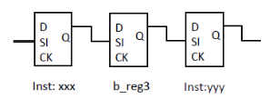
In the example below (Figure 4), the original scan chain sequence is:
xxx/Q → b_reg3 → yyy/SI
After determining an appropriate SDFF location (such as b_reg3), users can connect the new SDFF to that location directly, and declare the connection of the chain members, using the following commands.
insert_reg_into_scan_chain mid_inst/ez_reg[1] b_reg[3]
insert_reg_into_scan_chain mid_inst/ez_reg[0] mid_inst/ez_reg[1]
insert_reg_into_scan_chain mid_inst/ez_reg[2] mid_inst/ez_reg[0]

Figure 4: Original scan chain sequence
Note that insert_reg_into_scan_chain defines a sequential operation, and it must be declared rear member first (b_reg3) before proceeding to the front member (ez_reg2). The resulted sequence is (as shown on Figure 5)
xxx/Q → ez_reg2 → ez_reg0 → ez_reg1 → b_reg3 → yyy/SI

Figure 5: Example of manual scan chain stitching
(4) Removing DFF(s) That Are Connected into Scan Chain
Users can comply with their own DFT design rules more flexibly by manually removing SDFFs that have already been stitched into the scan chain.
Users can specify how to keep or remove a specific register in the scan chain. This usage is a suitable solution for these scenarios:
a. Timing issue, or
b. P&R congestion issue, or
c. User-defined special scan chain function, or
d. Clock generating circuit.
The following command can prevent specific DFF(s) from being stitched into the original scan chain:
exclude_add_sdff mid_inst/ez_reg[1]
Conversely, the following command prevents specific registers from being removed:
exclude_remove_sdff redundant_occ/shift_reg
Summary
With ScanChainECO automated flow, modifying scan chain in a functional ECO task has become simpler. The benefits of DFT features include:
● By automatically stitching and balancing scan chains, designers no longer need to manually trace the characteristics of each individual SDFF, even when working with large quantities.
● Diverse controllability options provide flexible solutions for achieving DFT-related design requirements.
● Performing logic ECO and fixing scan chains together in one single EasylogicECO flow greatly reduces functional ECO turnaround time.
About the author
Kager Tsai
Vice President of Technical Support, Easy-Logic Technology
Since joining Easy-Logic Technology in 2021, Kager has been instrumental in leading his team to offer top-notch technical support to users globally. With 18 years of experience in the CAD industry and has worked for companies such as SiS, MStar, MTK, and Cadence, Kager is proficient in the ASIC front-end tool flow, especially in formal verification and ECO-related applications. Kager also participated in the development of many advanced ECO tool features. |
|