Post-Mask ECO的补丁设计上预备资源的应用策略
下载文档Post-mask Functional ECO的资源策略
EasylogicECO 白皮书 WP-PMR-01 | Functional ECO (Engineering Change Order) 是用于修改现有 ASIC 设计的增量式设计方法。一旦 RTL 代码被修改用来改变现有ASIC 功能,ECO 过程会修改现有网表的一部分,以与修订后的 ASIC 功能保持一致,同时保留大部分网表的完整性。
近年来,由于 ASIC 设计的复杂性增加和更短的项目周期,Functional ECO 的需求变得越来越普遍。当需要更改 RTL 时,重新启动整个设计总是导致项目延误。成功的 ECO 任务为迅速纳入所需的更改提供了一条捷径。在设计的后期阶段(已完成P&R或已流片),成功的 ECO 任务可以显著减少项目延误,从几个月缩短到仅几天,同时保持相同的质量结果。
本文研究了Metal ECO 任务相关的可用备用资源,并探讨了 EasylogicECO 需要使用的额外资源。 |
Post-Mask ECO 简介
Functional ECO 过程分为两个主要方面:
1.Pre-layout ECO
2.Post-layout ECO
Functional ECO 任务所需的必要修订取决于设计项目所处的阶段。Pre-layout变更涉及对设计逻辑和特定设计要求的相关实现进行修改,如低功耗单元、扫描链网表、P&R 数据。另一方面,Post-layout变更仅限于金属层,旨在重新连接可用的逻辑资源(称为Post-layout ECO 或Metal ECO)。图 1 说明了需要修复的数据类型。
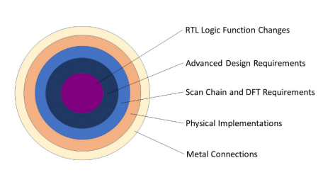
图1:在post-mask ECO任务中可能需要更改的数据类型
在本文中,我们将重点放在Post-mask ECO 中的补丁实现和资源策略上。
Post-mask Functional ECO 任务中的补丁实现标准
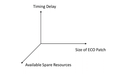
高效的补丁实现算法需要考虑三个因素:
1. 修订后网表的时延, 2. 用于创建补丁的可用备用资源, 3. ECO 补丁的大小。
已修订网表的时延,来源于对原始网表的分析,它代表要实现的目标时延。修订后功能的补丁逻辑必须使用现有的备用资源来满足时延要求,这些资源在单元功能、延迟、位置和数量方面都是预先确定的。因此,可用资源的数量最终决定了补丁的结果,包括时延和补丁大小。
这就是为什么我们将资源策略作为Post-mask ECO 成功的基础。 |
图2:补丁实施过程中的权衡 |
Post-mask ECO 的备用资源概述
如果一个设计已经完成布线或已经出片(即Post-mask),那么ECO会很大程度的依赖于补丁实现的可备用资源。实施补丁所使用的资源需要使其物理位置处于需要修订功能的 ECO 网络附近。
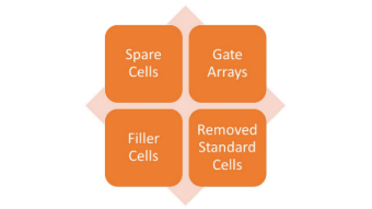
Post-mask Functional ECO 的备用资源包括四个逻辑单元:
1. 备用单元(Spare cells) 2. 门阵列(Gate arrays) 3. 填充单元(Filler cells) 由于 ECO 而与原始功能脱离的标准单元(standard cells) |
|
处理备用资源的传统方法
传统方法涉及两种类型的备用资源:
1.备用单元(Spare cells)
2.门阵列(Gate arrays)
(1)备用单元(Spare cells)
备用单元指的是一组预先设计的标准单元,它们最初并未在主设计中使用,但被保留用于post-mask修改。它们提供了灵活性,使功能修改不需要大的布局变更。用于Functional ECO 的备用单元的具体类型取决于设计的特性,控制逻辑和组合逻辑在Functional ECO 情境中经常需要不同类型的逻辑单元。
可以放置的备用单元数量是有限的,需要谨慎分配,否则可能导致对可用资源的不充分利用。
(2)门阵列(Gate arrays)
门阵列涉及预定义的基本逻辑门数组,可以通过应用金属层连接来实现特定功能。门阵列可用于针对性更改,无需进行大量的设计迭代。然而,同标准单元相比,门阵列可能具有更高的面积和功耗开销。它们的使用需要进行仔细规划和设计整合。由于它们的较大尺寸,门阵列通常被放置在远离密集布线区域的地方,这可能导致时延问题。
备用单元和门阵列在时延、面积使用和功耗方面各有利弊。如何选择取决于特定的设计应用,因为不同的应用可能更适合特定的资源组合。这份白皮书仅关注于展示基本概念,并不深入探讨设计策略。
EasylogicECO 使用的额外备用资源
由于可用资源的数量对 ECO 的成功至关重要,EasylogicECO 采用了创新的算法来增加补丁实施的资源。EasylogicECO 使用以下两种额外资源:
1. 填充单元(Filler cells),
2. 从原始网表中分离出来的标准单元(standard cells)。
这种先进的方法显著增加了资源的数量,并增强了在post-mask ECO 中取得成功的可能性。
(1) 填充单元(Filler cells)
填充单元是为了提高制造良率而加入版图的额外单元。它们具有完整的门结构和指定的 VDD/VSS 引脚,遵循标准单元的布局规则。但它们缺乏逻辑功能,因为它们的金属层有意地保持开放。
与多层金属、扩散和金属1层建立连接的填充单元可以用于构建功能型门。与配置门阵列一样,填充单元使用金属连接层将单元配置为特定功能。这项技术非常适合涉及小补丁而无需进行大量的设计修改的Functional ECO。
(2) 被分离的标准单元(standard cells)
Functional ECO 案例通常涉及添加新的逻辑门,同时删除一些旧的逻辑门。被移除的门通常位于 ECO 点附近,使其成为进行补丁的最佳选择。重复使用这些从原始网表中分离出来的标准单元引入了一个有趣的概念,这在布线延迟和设计灵活性方面提供了极好的便利性。
考虑以下示例:一个 ECO 任务涉及添加30个门来创建一个补丁,同时分离20个原始门。EasylogicECO 检查移除的电路,如果这些被分离出来的20个门中的10个可以被重复利用,它将所需的备用单元数量从30减少到20,这种方法在某些情况下可以使成功率翻倍。
选择最佳利用备用资源的技术
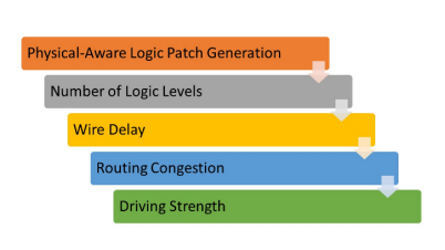
EasylogicECO 采用了一个创新算法来优化post-make Functional ECO 任务的时延。除了利用额外的备用资源,补丁实现过程还纳入了特定的资源选择技术,以确保获得最佳的优化结果。如图3所示,这些技术包括:
1. 物理感知的补丁生成 从 LEF/DEF 输入和库文件中获得的设计和可用备用资源的物理信息被用来生成满足设计时延要求的补丁。 2. 逻辑层数 为了满足时序要求,EasylogicECO 通过分析原始设计和提供的物理信息,以确定适当的逻辑层范围。然后在补丁优化中使用此分析结果。
3. 布线延迟 由于布线延迟起着关键作用,EasylogicECO 通过利用网表中的物理信息和用户提供的备用资源来估算布线延迟。 |
图3:获得最佳补丁结果的资源选择技术 |
4. 布线拥塞
在单元选择过程中可人工加入可布线性的考虑,将拥塞因素纳入优化算法。这个因素会评估避开目标备用实例周围区域的连接门单元。
5. 驱动能力
根据扇出要求和估计的线长,post-mask补丁的单元会适当变化相对应的驱动能力。
结论
EasylogicECO通过利用额外的备用资源,并在post-mask Functional ECO的物理优化中考虑关键的时延因素,高效地提供了满足所需时延要求的补丁,同时最大限度地减少了工具执行时间。
关于作者
Kager Tsai(蔡宗智)
奇捷科技公司技术支持副总经理
Kager 于2021年加入奇捷科技,所率领的团队,在为国内外用户提供高质量技术服务支持的过程中,形成了完备的服务体系,积累了宝贵的知识经验。 Kager具有18年的CAD业界工作经验, 曾任职于矽统 (SiS) 、晨星(MStar)、联发科(MTK)、Cadence等企业。Kager擅长ASIC设计的前端工具流程,尤其是形式验证及ECO相关应用。 Kager参与了奇捷科技ECO产品很多先进功能的研制,并协助众多客户在设计环境中完美导入ECO设计流程,成功完成ECO项目。 Kager 曾获得国立中央大学的电机工程理学硕士学位。 |
|

完美解决各种设计流程中
可能出现的逻辑错误
公司:奇捷科技(深圳)有限公司
电话:+86-755-82556054
地址:深圳市福田区福保街道市花路5号长富金茂大厦1号楼2110
邮箱:info@easylogiceda.com