基于RTL以及全模块操作的功能性ECO设计方法论
下载文档基于RTL的全模块Functional ECO方法论
EasylogicECO 白皮书 WP-RTL-01 | ECO是一种增量式设计方法(incremental design method),用于修改现有的ASIC设计。当新的RTL代码改变了原有的ASIC功能,可以通过ECO尽量少地修改旧的网表,包括实例 (instance)和连接 (connection),并在保持网表大部分内容不变的情况下,实现新的ASIC功能。这个过程被称为逻辑功能变更(Functional ECO)。
近年来,随着ASIC设计的复杂性增加,项目周期缩短,以及市场需求不断变化,ASIC设计阶段的功能变更需求日益频繁。一旦设计地更改不可避免的发生,项目的延误就会经常发生。然而,ECO提供了一条能够快速实现设计更改的有效途径。在项目的后期阶段,如果ECO成功,项目的延误可以从几个月缩短到仅几天,同时保证了相同质量和设计流程的完整性。
虽然ECO能够为ASIC项目带来了巨大的价值,但实施逻辑功能变更仍是一项充满挑战的任务。本文将探讨当前逻辑功能变更解决方案中存在的问题,并提出一种新的设计方法。
|
简 介
虽然逻辑功能变更可以为芯片的成功带来巨大的商业价值,然而它本身就是一个极为复杂的过程。即使是细微的RTL代码改动也可能在芯片设计的不同阶段产生巨大的差异,芯片设计师需要处理ECO带来的各种影响,而这些影响的复杂性有时会超出他们能够独立处理的能力。这种相对高复杂性的case,容易导致很多项目负责人对逻辑功能变更望而生畏,他们往往迅速得出无法ECO的结论,认为这种高复杂度的修改,只能重新设计。
1. 修改处于设计流程各个阶段的电路 2. 评估现有电路设计需要更改的范围,并实施所有必要的修改 3. 最优化需修改逻辑的cell数量
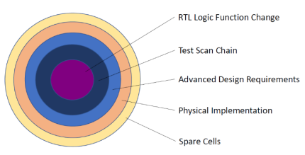
逻辑功能变更任务的起点是RTL代码的更改。根据不同设计阶段的ECO要求,设计师需要处理的不仅仅是设计逻辑的变化,还包括扫描链相关的实现、低功耗单元特定的设计需求、标准单元布局与布线的相关实现、以及备用单元(spare cell)的相关实现(如设计已经制造或接近完成)。图1显示了需要修复的设计数据类型。 |
Figure 1: Ripple effect of the ECO-related design changes |
设计师面临的另一个挑战是判断ECO对设计的影响程度。举一个简单的例子:修改一个IP的RTL,而该IP在设计中被实例化多次,并且功能更改发生在IP的接口部分,对这个更改进行ECO往往会导致设计的大范围改动。
本白皮书将主要关注上述挑战的第二部分,即评估设计变更影响的范围并进行修复。
业内常见Functional ECO的相关问题
大多数设计师在执行逻辑功能变更任务时会遵循一些旧准则与遭遇某些状况:
1. 利用门到门(G2G)比较来识别功能差异;
2. 将设计划分到子模块级来进行ECO操作;
3. 忍受漫长的工具执行时间和缓慢的任务周转。
综上所述,ECO本身就是一个复杂的过程。导致ECO任务困难的根本原因,是现行的ECO设计方法仍使用旧思维与流程,导致结果与过程都可能呈现令人无法接受的状况。接下来,我们将针对上述每个状况,深入分析相关的问题。
(1)使用门到门(G2G)比较来识别功能差异
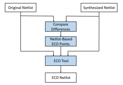
基于两个门级网表(图2)进行功能比较被视为一种较直观、更符合逻辑的方法。其中,新综合网表是从修订后的 RTL 中生成的。这样的比较方式使得人们更易于理解,因为原始网表是比较的基准,而综合网表与原始网表都是网表,用相同格式进行比较会更具合理性。但是以门到门(G2G)比较为基础的ECO方法总是伴随着两个问题:
原始网表中的信号难以追踪的问题这是由于综合过程中的逻辑优化,综合网表可能会出现意外的变化,甚至有时RTL中的信号在对应网表中根本不存在。我们来看一个简单的例子: |
Figure 2: G2G netlist-based methodology |
// Original RTL module adder ( input [3:0] operand_1, input [3:0] operand_2, input [3:0] operand_3, output [4:0] result); wire [4:0] n1; assign n1 = operand_1 + operand_2; assign result = n1 + operand_3; endmodule | // Revised RTL module adder ( input [3:0] operand_1, input [3:0] operand_2, input [3:0] operand_3, output [4:0] result); wire [4:0] n1; assign n1 = operand_1 + (operand_1 + operand_2) ^ 4'b0011; assign result = n1 + operand_3; endmodule |
在原始RTL上对“assign n1”语句进行必要的ECO更改,这对在门级网表中定位n1信号提出了挑战。这是因为综合工具将信号进行了分解以减少面积。信号的缺失可以归因于以下原因:
1) RTL中的线n1是内部的,这意味着综合工具在正确组合输出函数的情况下可以灵活地地利用它。根据优化的目标,综合工具可以选择保留信号n1或将其分解为最小项以构造输出函数。
2) 无论RTL中的信号n1是否被保留,它在综合后的网表中的名称都可能会被更改。这使得设计师在网表中追踪相应的信号变得具有挑战性。
上述ECO任务是根据RTL中n1的新规范(specification)来修改输出功能。因此,设计师可能需要花费大量精力追踪影响输出结果的所有信号路径,来创建最小的补丁。
2、补丁尺寸较大
当原始网表、综合网表或两者都已从网表中优化一些RTL中的信号时,可能导致严重的问题。门到门的等效性检查可能会因为不同的优化选择而导致判断出错误的差异,从而产生错误的ECO点。而ECO最终的结果往往是一个不必要的大型补丁,这通常容易导致时序无法收敛。
(2)子模块级ECO所遭遇的问题
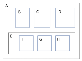
为了理解讨论中使用的术语,图3显示了一个完整的ASIC设计在后端的分割模块。设计层次结构的顶层是A(整个芯片)。整个芯片被划分为逻辑模块B-H,其中B、C、D、E作为A的母模块(partition-modules),F、G和H则为(母模块下的)子模块(sub-modules)。 |
Figure 3: Example of ASIC design hierarchy |
基于模块的设计方法使设计师能够以分层的方式开发芯片,每个母模块都可以独立设计和测试。考虑到效率和质量,系统母模块的大小通常建议低于500万个逻辑单元。
由于G2G比较导致的高风险,例如潜在的错误和漫长的时间执行,大多数设计师在处理逻辑功能变更任务时,更喜欢使用分而治之的方法。设计师在每个子模块内分别执行ECO任务,而子模块的大小取决于两个方面:用户能接受的G2G比较时间和ECO任务运行时间。
除了仅涉及简单局部更改的ECO案例,在较为复杂case下,划分子模块的方法无疑在ECO周转时间、人员参与和结果质量方面都带来了不小的挑战。原因如下:
1. 提取边界约束
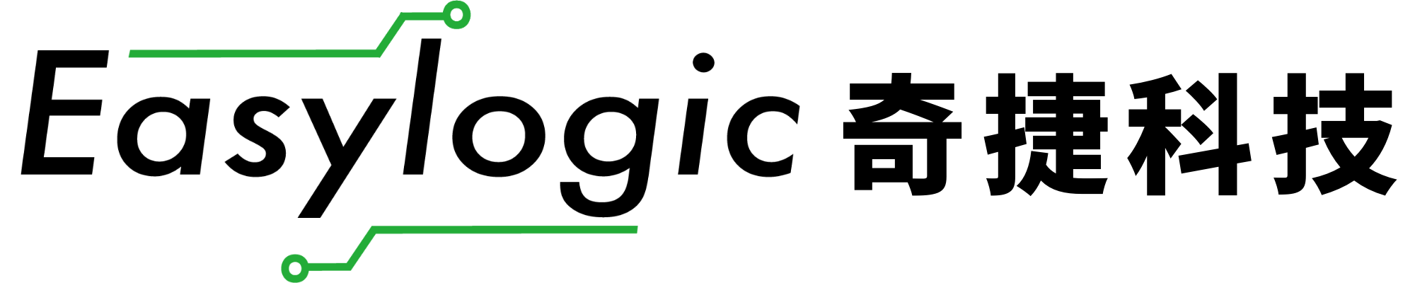
下面的例子(图4)演示了用户在ECO任务过程中面临的挑战。
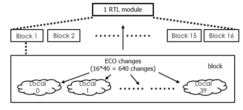
Figure 4: Example of the scope of ECO impact
一个IP在一个block中实例化(instantiate)了40次,这个block在顶层中又被复制了16次。那么在ECO任务中,相对应地就需要检查IP中此一行RTL代码更改所带来的640次ECO任务,来确保设计的完整性。
这里的挑战在于为参与ECO的每个block都抽取边界约束(extract boundary constraints)。只有保证每个block的边界约束正确,我们才能确保逻辑功能、DFT和其他设计要求不被错误处理,不至于导致多余的修改甚至错误的ECO结果。边界约束是从block的边界条件,如block间连接(引脚约束)、时钟缓冲树(clock buffer tree)、DFT相关功能...中萃取出来的。设计师在为每个单独的block手动提取边界约束时,常容易犯错。最难的地方,就在于如何保证抽取出来的质量是可信与正确的。
1. 重复操作负担
除了为逻辑功能提取边界条件外,设计师还经常发现自己在多个设计步骤(如形式验证、DFT等)中需不停重复类似的工作。这些手工操作流程一旦不小心犯错,常导致改正错误需要更多的精力与时间。
下表1总结了在子模块级别执行ECO操作的优缺点。
Sub-Module ECO Methodology | Analysis |
Quality of result | Good if associated changes are within a sub-module |
Execution time of ECO tool | Acceptable |
Synthesis run time of revised RTL | Acceptable |
User’s design knowledge required | • Number of design blocks involved in the ECO • Tracking design impact across block boundaries • Boundary conditions of each block to identify |
Developing block constraints | Tedious and time consuming, repeating the process for each sub-module with varying constraint conditions. |
Formal verification | Tedious and time consuming, repeating the process for each sub-module with varying constraint conditions. |
Table 1: Analysis of the ECO design work based on sub-modules
(3)忍受漫长的工具运行时间和总ECO周转时间
除了设计师手工操作消耗的时间外,ECO工具运行时间也对总ECO周转时间产生了重大影响。如前所述,设计师在决定每个子模块大小的时候会参考ECO工具的运行时间,通常会为了避免过长的运行时间而减小单个子模块的规模。然而,为了减少工具运行时间而刻意使用较小的子模块却又往往导致设计师手工操作量与犯错的可能性增加(图5)。
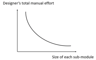
Figure 5: Trade-off between size of sub-module and designer’s effort
工具运行时间包括3个主要部分:
1. 对修改后的RTL进行综合,生成综合网表
2. 在原始网表和综合网表间进行逻辑等价性验证(formal verification),以确定ECO点
3. ECO工具创建补丁,同时为设计流程中的其它工具准备ECO增量指令(incremental instruction)
一旦成功提取每个block的约束条件,在不并行处理的情况下,总ECO周转时间就会是上述3部分之和乘以需要ECO更改的block的数量。分解后如下:
1. 综合和LEC运行的周转时间
RTL的逻辑综合和G2G等价性检查需要大量的执行时间。 为了协助逻辑等价性验证还需要准备约束和参数。此外,设计师还可能需要人工介入formal 验证过程来消除工具误判的不等点(non-eq),直到所有的误判都被修正。在这个阶段,设计师会假定formal中所有非等价结果都与ECO有关。
然而,如果非等价结果中存在任何ECO points是明显无直接关系于RTL的变动,它仍将被工具视为必须的更改,并导致创建不必要的补丁,即使实际上这些错误,根本不需任何的变动,单纯只是因为综合最佳化方法不同所产生的一种现象。
2. ECO工具执行时间
子模块的ECO运行时间从几个小时到几天不等。通常情况下,当子模块的算术逻辑或电路复杂性增加时,工具运行时间会呈指数级增长,这是因为工具在功能、时序计算和资源限制之间挣扎着平衡。在很多情况下,最终结果会是ECO失败。当一切努力都白费时,用户常感到深深地挫败。
分 析
从前面的讨论中可以得出,现代逻辑功能的变更方法应该要有效解决以下问题:
1. G2G比较容易产生的错误ECO点
2. 必须将完整模块划分为小块进行ECO(避免运行时间过长,甚至无法得到结果)
3. 不可控的超长周转时间
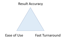
换句话说,逻辑功能变更方法应提供以下交付成果(图6):
1. 结果准确性 准确地找出需要的更改并添加补丁,不因为错误的ECO点而添加不必要的电路
2. 易用性 在整个设计流程中最大程度地减少设计师所需的知识和人工操作 |
Figure 6: Required solution deliverables |
1. 积极降低人工犯错的可能性
尽可能让所有的ECO工作,都由工具完成,不需额外的人工处理
2. 快速周转:
从RTL更改开始,到芯片整个逻辑和物理实现过程最短的ECO周转时间
值得庆幸的是,在过去的十年里,逻辑功能变更方法在电子市场的快速发展、对ECO解决方案的需求增加以及EDA供应商的积极响应的一起推动下取得了显著的进步。此外,专门为ECO要求量身定制的逻辑优化技术进一步推动了这一领域的进展。其中包括先进算法、自动化流程和调试功能的引入。ECO工具的用户将会从新兴技术中受益,使其ECO任务成功率大大提高
解决方案:洞察现代ECO技术行业的前沿
先进的逻辑功能变更技术提供以下三个关键特性,以帮助节省工程资源、缩短项目时间、并尽量减少用户参与:
1. 基于RTL差异的功能比较
2. 不需要子模块划分的ECO操作
3. 短的工具执行时间和总ECO周转时间
让我们来看看细节:
(1) 为什么基于RTL逻辑功能差异比较的方法会更好?
基于RTL的ECO设计方法(图5),即RTL-to-RTL (R2R)比较,在定位逻辑功能变更的时候比G2G方法有更高的精度。RTL比较的ECO流程提供了以下强大的优势:
1. 更高的ECO更改点(eco point)精度
R2R比较可以避免在G2G中容易发生的功能识别错误,并避免网表准备过程中,由于综合工具采用不同的综合策略而导致的不等点(non-eq)误判。
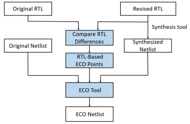
Figure 5: RTL-based ECO methodology
此外,在G2G比较中,等价性检查可能会导致工具运行意外中止。因为修改后的逻辑功能可能会改变综合网表与原始网表的算术逻辑架构。相比之下,R2R在识别ECO更改点方面可能是一种更高效且低错的方法,而G2G通常会更浪费时间和精力
1. 更高的设计自由度
现代ECO技术已经发展到可以准确地知道RTL信号在门级网表中是如何表示的。在前面讨论的Verilog设计示例中,设计师可以自由改变n1在RTL中的功能,而不用担心它在门级网表中会被如何优化甚至是消失不见
2. 更小的补丁尺寸
基于RTL设计差异的分析为ECO策略提供了准确的行动指南。全面识别将RTL代码转换为门级网表的RTL映射和优化操作,对于识别下游ECO更改点至关重要,最终将通过优化补丁逻辑来实现更小的补丁数量
(2)基于模块的ECO操作优势
萃取每个子模块的边界条件对工程师来说既耗时又容易出错,因此不进行子模块划分而是基于模块整体的ECO流程,可以很大程度避免设计师花费了过多时间和精力,却得不到好的结果。模块整体的ECO流程明显的更可显著地提高结果的准确性。
为逻辑功能变更应用量身定制的专用算法发展,显著降低了工具运行时间,哪怕是对超大型芯片的设计进行ECO也同样如此。
回顾图4中的示例,自动ECO解决方案可以通过成功实现以下两个关键要素,在整个模块上无缝执行ECO任务:
1. 跟踪640个设计模块的影响范围,以确定所需的更改
2. 使用创新的逻辑综合和优化算法提取所有更改的条件
提取的条件被转换为自动ECO约束,然后由ECO创建整个模块的优化补丁。
同样地,基于模块整体的操作适用于post-ECO验证。建议在更改后的RTL和ECO网表之间进行覆盖整个模块的等价性检查。
基于R2R比较和不划分子模块的ECO流程,为设计师提供了一种更理想与进步的方法来应对挑战。
(3) 最小化工具运行时间和ECO周转时间
ECO任务的周转时间至关重要。与正常的ASIC设计过程不同,逻辑功能变更通常是伴随预定义条件和有限资源的任务。由于这些任务有显著的时间压力,但成功率又难以预测,因此压缩ECO过程所需的时间对ECO任务的有效执行具有战略意义。
在项目转入布局阶段后,逻辑功能变更的资源变得有限。与逻辑阶段相比,布局阶段与物理实现相关的任务变得更具挑战性。最具挑战性的情况是metal ECO,在此情况下,ECO的成功取决于ECO点周围可用的备用资源。此外,在布线与布局过程中,网表可能已经被优化或展平,并变得难于识别,这给ECO任务增加了另一层难度。
设计师对一个ECO任务的四个RTL更改版本进行了精心实验,这些更改产生了相同的逻辑功能。研究发现,版本4提供了最佳的ECO结果,其次是版本2,但版本2和版本3未能满足时序要求。
需要强调的是,设计师仅根据RTL代码无法准确预测ECO结果,这凸显了进行全面评估以确定最有效解决方案的必要性。
下表2展示了ECO任务中一个引人注目的例子。
Revised RTL | Design Size (gates) | Patch Size (gates) | Recycled gates | Gate count change |
Version 1 | 3815 | 280 | 98 | +182 |
Version 2 | 3815 | 41 | 10 | +31 |
Version 3 | 3815 | 678 | 199 | +479 |
Version 4 | 3815 | 29 | 4 | +25 |
Table 2: Experimenting with multiple RTL code changes for the best ECO outcome
在这种情况下,工具的运行时间成为ECO成功的关键决定因素。快速评估ECO是否可行至关重要。如果RTL代码的更改没有产生预期结果,可能需要探索RTL不同的修改方法以完成ECO任务。极短的ECO操作时间对于实现此目标至关重要。
为了实现最短的ECO周转时间,可以部署一些技术:
1. 基于R2R的功能比较
几乎所有ECO流程都需要重新综合新RTL得到的网表,且必须执行R2R(比较修改后的RTL与原始RTL)或G2G(比较合成网表与原始网表)来识别ECO点。很明显,对比门级网表相对于R2R需要的执行时间更长得多
当设计尺寸较大时,与G2G相比,R2R在等价性检查中消耗的执行时间通常少10倍或更多,尽管执行时间取决于特定设计的自身状况,例如寄存器和门的数量,算术逻辑复杂性以及作业环境设置,部署的工具以及应用的约束等。但通常即便是对于复杂的模块,R2R等价性检查也可以在几个小时内完成,而相同大小的G2G等价检查可能需要几天。
R2R比较提供了可预测且快速的运行时间,同时确保了可扩展性。 R2R比较的结果,即准确且简洁的ECO点,进一步加快了ECO工具的执行。
2. 补丁大小与时序精度之间的权衡
ECO算法应优先考虑补丁大小而非时序精度,并在这两个因素之间取得权衡。该方法为设计师带来了显著的价值:
1)在极短的时间内就得知改动后的RTL能否满足各项技术要求,这远比真正完成时序优化才得知结果要节省时间
2)允许功能相同的多种RTL不同方案频繁地迭代测试
3)在后续的P&R步骤中进行最小的更改
有3种主要技术有助于实现这一目标:
1)优化优先级
减少补丁中的逻辑门数量可以显著提高时序收敛(timing closure)的概率,特别是在与布局(placement and routing)相关的ECO过程中。
2)时序估计
通过精心设计的时序估计算法来指导trade off过程是实现高效ECO的关键部分。先评估补丁的logic depth的合理目标范围,再把这个结果当作ECO的优化过程的约束条件。
3)物理感知
ECO映射和最优演算法通过仔细选择物理ECO点附近的门类型来优化逻辑门的logic depth、资源功能和物理位置,最终创建最短的逻辑路径。
3. 为后续工具生成有效指令
由于ECO过程涵盖了整个ASIC设计流程,从RTL代码到GDS出片,它涉及到各种关键设计工具,并需要与其他工具进行信息交换(图6)。
Figure 6: Required ECO data integration in an ECO flow
ECO工具应始终为后续设计步骤生成操作指引,例如ECO TCLs可用于后续的P&R工具,使用户能够轻松将指引信息转换为下游工具的约束。
对紧密集成的自动ECO设计流程来说,无缝适应混合的工具环境至关重要,以实现高效执行ECO任务并最大限度地减少总周转时间。
结 论
在仔细分析了现存的问题之后,逻辑功能变更对于使用传统方法的设计师来说是一个重大挑战。然而,我们的研究表明,新兴的ECO技术具有正确的方法来克服这些挑战,并可以实现准确的ECO结果和短周转时间。
我们相信,通过实施基于R2R的全模块逻辑功能变更,ASIC设计师将能够专注于功能更改本身,这不仅会提高他们的生产力,而且还有助于提高他们ASIC产品的竞争力。此外,我们的分析表明,基于R2R的全模块逻辑功能变更是一种更稳健、更具成本效益的选择,而且可以轻松地集成到现有系统中。
总之,利用逻辑功能变更进行设计将会是ASIC公司提高产品竞争力和提高组织盈利能力的重要手段。市场上已经可以获取采用创新ECO方法的商业ECO工具,如奇捷科技(Easy-Logic Technology)提供的EasylogicECO。我强烈建议ASIC设计师认真考虑采用这种新的ECO工具,以优化他们的设计过程。
关于作者
Kager Tsai(蔡宗智)
奇捷科技公司技术支持副总经理
Kager 于2021年加入奇捷科技,所率领的团队,在为国内外用户提供高质量技术服务支持的过程中,形成了完备的服务体系,积累了宝贵的知识经验。 Kager具有18年的CAD业界工作经验, 曾任职于矽统 (SiS) 、晨星(MStar)、联发科(MTK)、Cadence等企业。Kager擅长ASIC设计的前端工具流程,尤其是形式验证及ECO相关应用。 Kager参与了奇捷科技ECO产品很多先进功能的研制,并协助众多客户在设计环境中完美导入ECO设计流程,成功完成ECO项目。 Kager 曾获得国立中央大学的电机工程理学硕士学位。 |
|

完美解决各种设计流程中
可能出现的逻辑错误
公司:奇捷科技(深圳)有限公司
电话:+86-755-82556054
地址:深圳市福田区福保街道市花路5号长富金茂大厦1号楼2110
邮箱:info@easylogiceda.com